
This video is intended for those who already manages the 8-bit architecture of Arduino, but it is still difficult to master 32-bit MCUs.
Hello everyone!
In our first lesson we will meet:
- the TITAN board structure ;
- the CC430F5137 MCU with MSP430 core;
- with SmartRF Studio software from Texas Instruments.
So,
The TITAN board is a pin-compatible with Arduino board with a built-in CC430F5137 target MCU and a programmer-debugger, which is implemented on the MSP430F5528 controller. As you may have guessed, the programmer-debugger has the same core as the target MCU. This choice is not accidental. Texas Instruments provides the programmer-debugger source codes for the EZ-FET Lite family, which are available on the Texas Instruments website. This part of the board is the programmer-debugger.

And this part is the target MCU with its environment.

Field for custom items
Custom button
Quartz 32768 Hz
Custom led
Quartz 32768 Hz
High frequency U. FL connector
Part of the radio frequency (433 MHz by default)
The MSP430 core has a wide selection of built-in hardware. You can find the general structure in the Texas Instruments reference documentation.
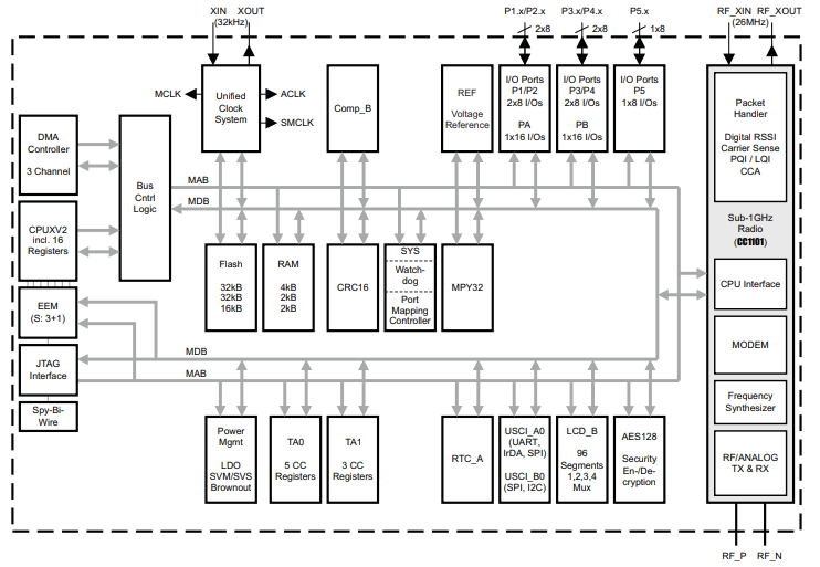
If you carefully study this structure, you will notice a stand-alone unit marked CC1101. This is not a mistake. This MCU really contains two “chips”. And in my opinion this is the best solution of Texas Instruments
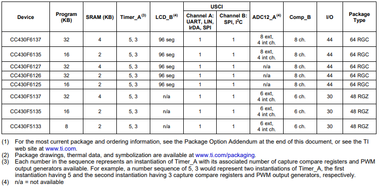
The TITAN uses the CC430F5137 MCU and contains 32KB Flash and 4KB RAM.
The CC430 MCU family is presented in the table that you can find in the Texas Instruments reference documentation.
I want to pay attention to the system “port mapping”, which is not so obviously described in the documentation. This system allows you to reassign functions practically to every I/O port. What does it look like? For example, you have decided to use UART pins, which are not intended for this by default. The reassignment system helps you do this software-based with just four lines of code. Cool, isn’t it? In further lessons we will definitely apply it!
But first, let’s connect TITAN to SmartRF Studio and try to create a regular generator at 433MHz.
Start SmartRF Studio and see the following window
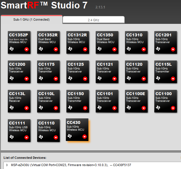
Mind that program has found the TITAN (bottom line) and automatically highlighted CC430 menu. Double click on this menu and go to “Device Control Panel”. Configure the program at the beginning of the range 433 MHz, exactly at 431.120514 MHz as shown in the picture.
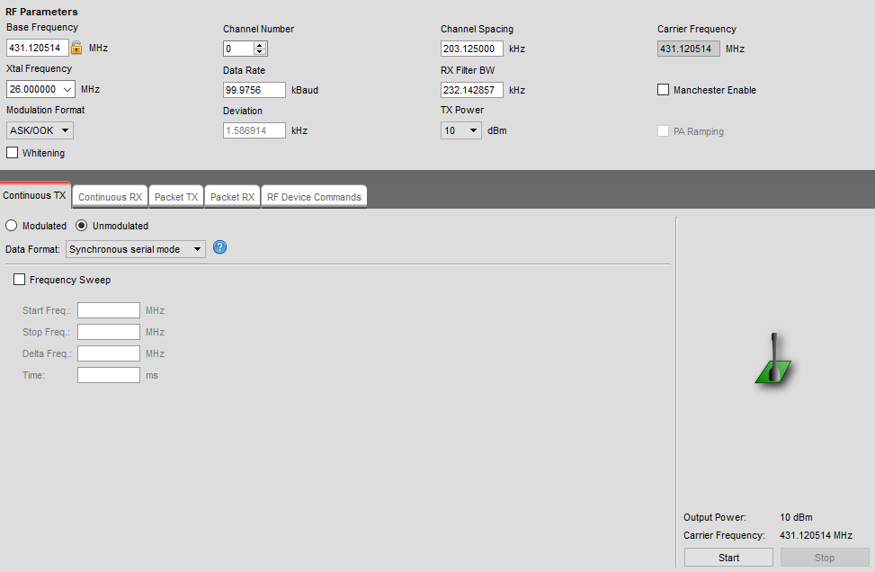
Connect TITAN to the spectrum analyzer (do not forget to put the equivalent load of 50 Ohm) and press the “Start” button in the program. On your spectrum analyzer you will see a picture like this.

Do not be afraid that the peak falls on a slightly shifted frequency. 431.120514 MHz is the central frequency of the channel, and we “pass” only zeros. That’s the reason of shifting.
Congratulations! You’ve just created an RF generator.
If you have two TITAN boards, you will be able to experiment with packet data modes, “sniffer” mode and much more. In our further lessons we will tell you how with the help of TITAN to create your own programs using data transfer.
And in the next lesson, we will meet two development environments that offers Texas Instruments absolutely for free.
Reference documentation at CC430F5137.pdf
Code Composer Studio Development Environment (CCS)