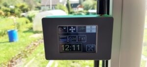
«TiTAN Stereo UV-METER»
Today we are exploring two interesting libraries in the Arduino IDE that we inherited from the panStam. The first library is for working with the address RGB LED WS2812 (NeoPixel).
The second library is for working with the radio. We’re going to use these libraries in our project “TiTAN Stereo UV-METER”.
Some might say, ‘There are a lot of such indicators on Arduino!’ But the question is, ‘How many of those are actually WIRELESS indicators?’
Here’s what we should get. https://youtu.be/y6rfHY3C-dI Let’s start from the beginning.
We’ll need an RGB-LED strip compatible with WS2812, for example, SK6805 as we have used here. Keep in mind that these LEDs need a power supply of 5 Volts and about 1 Ampere per meter, so do not choose a very long strip that will consume a large amount of energy. We’ve chosen a 2-meter strip with 120 LEDs.
We hope that you have already set up the Arduino IDE as we described in the previous post and tried out the example with the flashing LED.
Our next step is to download the example from panStam, which we will find in “File – > Examples – > Examples for TiTAN 1.0 w/cc430f5137 – > ws2812 – > ws2812driver”.
The panStamp library does not provide port remapping, so we will use the P1.1 port included in the library to control the LEDs.
Why P1.1?
Because it is the output of the SPI interface, and it’s the easiest and fastest way to form a control protocol for such RGB-LEDs.
Here’s what we’ve got.

Before uploading the project to TiTAN, you need to state how many LEDs there are in your strip. This is specified in the line WS2812STRIP strip(120);
In the library “ws2812.cpp” there is one unfortunate mistake. The file is located in
C:\Users\<strong>{user_name}</strong>\AppData\Local\Arduino15
\packages\panstamp_nrg\hardware
\msp430\1.1.0\lib raries\ws2812\
You need to find and remove the comments from the line “//while (!(UCB0IFG & UCTXIFG)); ” in this file.
Let’s compile our example and upload it to the TiTAN Board.
This is how it’s done. Have you got the same result? https://youtu.be/SdI7hJAXIkk
Let’s continue.
Let’s put aside the RGB-LEDs for a while and start working on the analog part of our project.
As we set a signal to the input from the headphone connector, the amplitude of this signal will be quite small. And with the ADC’s internal reference voltage, weak signals will be difficult to measure. To correct this situation, we can make our own reference voltage source on a variable resistor, which we’ll use to adjust the sensitivity. Connect it to the port P2.5. And also connect the left and right audio channels to the ports P2.0 and P2.1.
This is the scheme we should get.

Let’s move on to programming the analog part.
We have to disappoint you a little bit that the panStamp package does not involve the use of an external reference voltage and parallel multiple high-speed ADC measurement. This is hidden in the body of the “analogRead ()” function. Each time (!) when this function is started, the analog input is configured, the
ADC registers are configured as well, the MCU is waiting for the system clock to finish 1100 cycles, the value is read after the measurement, and then the ADC is disabled. Can you imagine what delays occur with 100 measurements?
In order for us to have access to the high-speed and parallel measurement over two channels at once, we need to initialize the ADC in the desired mode of the operation.

It’s OK if you find it difficult to understand what is written. One day you will be able to create such constructions yourself.
Now let’s create a function for getting analog data based on the results of 100 measurements.

When this function is called, the ADC will start, take the measurements on the channels A0 and A1, and by the end of each cycle, the maximum value will be saved. The main program will convert the received data into a number of glowing LEDs on each channel. This will happen every 20 milliseconds.

Please pay attention to the actions performed with the measured levels.
First, we filter out all low-frequency noise that is less than LOW_PASS and distribute the resulting value in the range 0..500 evenly. This is how we smooth out the results.
After that, we raise the value to the power of EXP=1.4 to emphasize the effect of a sharp increase in sound.
Then we form the effect of a smooth decrease in the level with a sharp decrease in volume and calculate the resulting length of the glowing LEDs.
Now we need to display all of this on our RGB-LEDs.
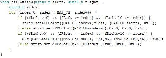
To do this, we need the “fillAudio()” function. Here it is.

The first 12 LEDs will be highlighted in purple, the next 18 in blue, another 18 in green, and the remaining 12 in red. The LEDs that are not included in the list of the glowing ones will be turned off.
You can download the complete program from our website https://titan-project.com/software/.
Check if you’ve done everything correctly.
All that’s left is to compile the project and upload it to the TiTAN Board.
By rotating the variable resistor, you can achieve the desired sensitivity at the selected music volume.
Congratulations!
You’ve got a “Stereo UV-METER”!
But what about the WIRELESS “TiTAN Stereo UV-METER”?
It’s very simple!
We’re almost there.
What’s left is to divide our project into 2 projects where the first one is the transmitter, and the second one is the receiver.
The first one is the transmitter. Add the following lines to it

The setup() function has to be slightly changed.

So it allows us to set the radio to the frequency of 433 MHz with all the necessary parameters. Instead of lines

Write

From now on, we don’t need this function, the LEDs themselves or anything related to the RGB-LEDs. We will only need all of that again in the receiver.
Note the definition of “SHOWMODE”. It can take the value of 1, 2 or 3. This is how we choose the algorithm for displaying on the LED strip.
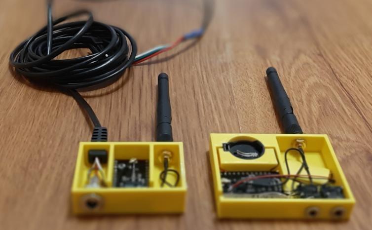
For convenience, we can use the TiTAN-I Board as a transmitter.
Let’s compile the project, upload it to the Board, and print the case.
Here’s what we get.
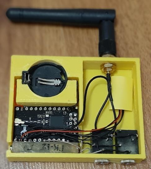
The circuit will be powered by a CR2032 battery. The current consumption will be about 20 milliamperes. This will allow you to work for about 8 hours on a new, high-quality battery.
Now it’s the receiver’s turn.
To make the radio work for reception, we need to add a function for processing data received over the radio.
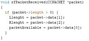
This function will replace the receiving of the data from the ADC.
The “packetAvailable” variable contains the number of the display algorithm on the LED strip which is specified in the transmitter.
Change the setup() function just like so:

Write the following in the main body of the program:

That’s all we need.
Or you can create your own. There are three of them. Or you can create your own.


The complete text of the program is available for download on our website https://titanproject.com/software/ .
For convenience, we use the TiTAN-I Board as a transmitter.
It’s time to compile the project, upload it to the Board, and print the case.
Here’s what we’ve got.
Now you can install the strip in a special holder for LED strips.
Let’s put together and switch on everything that we have made.

Congratulations!
You have just made a unique installation of lighting effects “TiTAN Stereo UVMETER”!