Microcontrollers with the MSP430 core have a unique opportunity to control the power and frequency of the core and the peripherals.
First, let’s look at how you can manage the power control. The “low-power module” (LPM) node is responsible for this function. This module has eight operating modes. In the operating modes of this node, three main needs are taken into account:
– Ultra-low power;
– Speed and channel capacity;
– Minimization of individual peripheral consumption.
All power management occurs by resetting or setting the CPUOFF, OSCOFF, SCG0, and SCG1 bits in the SR register. The advantage of this power control is that the current operating mode is stored on the stack when an interrupt occurs. At the end of the interrupt, the main program returns to the set power mode. The interrupt handler can also change the power mode on exit by manipulating the stored value of the SR register on the stack.
If any bit of the SR register is changed, the selected mode takes effect immediately.
The rules for switching from one power mode to another can be found in the document “CC430 Family User’s Guide (Rev. E) ” chapter 1.4 at https://www.ti.com/lit/ug/slau259e/slau259e.pdf

The illustration shows the main operating modes of the LPM node.
Now let’s consider the possibility of controlling the frequency.
The MSP430 core has three clock sources: MCLK (Master Clock), SMCLK (Sub-Master Clock), and ACLK (Auxiliary Clock). Any of these sources can be connected to each microcontroller peripherals independently of each other. The FLL (Frequency Locked Loop) and DCO (Digitally Controlled Oscillator) blocks are responsible for the formation of frequencies on these sources. In addition, the DCO can use an internal 10 kHz VLO (Very-Low-Power Low-Frequency Oscillator), an internal 32768 Hz REFO (Trimmed Low-Frequency Reference Oscillator), and external crystals at 32768 Hz and 26 MHz as a reference frequency source.
The combination of settings of these blocks will help to implement a very flexible and balanced system.
All nodes of the clock frequency generation are combined into the UCS (Unified Clock System), which you can get acquainted with in the document “CC430 Family User’s Guide (Rev. E) ” chapter 3 at https://www.ti.com/lit/ug/slau259e/slau259e.pdf
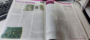
The development boards of the TiTAN family have a CC430A5137 microcontroller based on the MSP430 core. According to the documentation for it, the maximum frequency is 20 MHz. Is it so?
Let’s do an experiment to overclock the microcontroller to the maximum possible frequency.
Let’s write a program like this.

Connect it to the oscilloscope. On port P1.1 we will output ACLK (red line), and on port P1.4 we will output MCKL (yellow line).
In the program body, we will alternately output “0” and ” 1 ” on port P2.0. This will confirm that the microcontroller and its main program are working.
For full operation, select the LPM3 mode.
Here’s what we’ve got.

The ACLK period is ~720 nS – that’s about 1.39 MHz
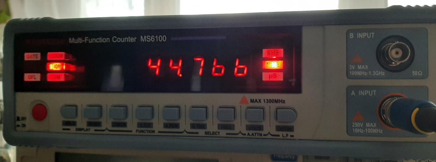
Since ACLK = MCLK/32, then probably MCLK=44.76 MHz? Wow!
Is it so? Connect the MCLK to the frequency meter.
It remains to check whether the MSP430 core itself works at the same time.
Connect it to the oscilloscope. On port P0.0, we will output pulses from the program (red line), and on port P1.1, we will output MCKL (yellow line).
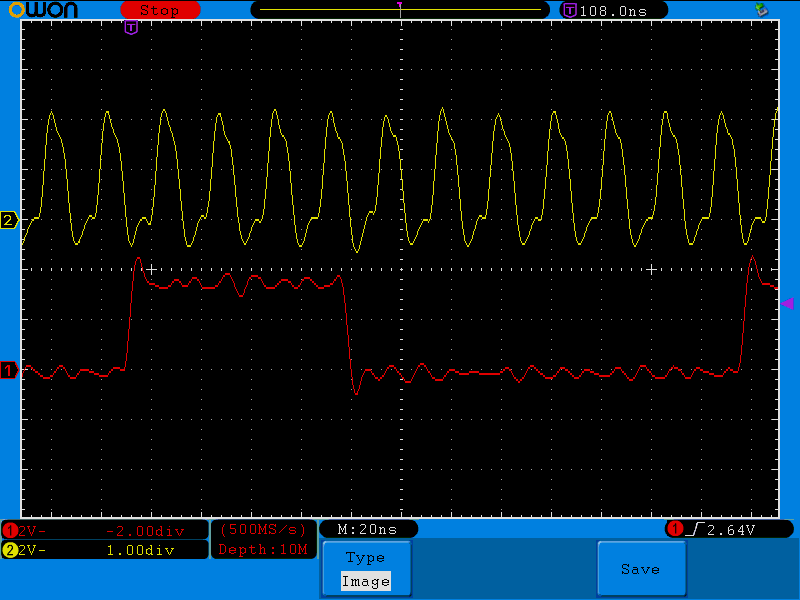
Wow! It works!
We can see that setting the port to “1” is 4 MCLK clock cycles, and resetting to “0” and repeating the cycle is 7 MCLK clock cycles.
Hence, we conclude that the MSP430 core can be overclocked almost 2 times very easily.
This trick will help developers learn new programming techniques on TiTAN boards.